A professional injection molding supplier prevents defects by controlling part design, resin condition, mold temperature, filling behavior, packing, cooling, ejection, and measurement as one production system. A wall-thickness change of more than about 40–60% can increase uneven shrinkage, while many engineering resins require moisture control below roughly 0.02–0.20%, depending on grade. In production, a 1–3°C mold-temperature shift or a small change in transfer position can affect dimensions on tight-tolerance parts. Stable molding depends on measured process limits, not repeated operator adjustment. Suppliers also use cavity balance checks, first-article inspection, SPC data, maintenance records, and lot traceability to prevent recurring short shots, sink, flash, burn marks, weld lines, and warpage.
Defect prevention normally begins before the mold is built because geometry determines how plastic fills, cools, shrinks, and releases from steel. Large thickness changes create different cooling rates, while thick bosses and ribs can hold heat well after surrounding walls have solidified. A common mold-design guideline keeps rib thickness near 40–60% of the adjoining nominal wall when surface appearance matters. Draft may start around 0.5–1° per side on simple polished surfaces, while textured surfaces often need more, depending on texture depth and resin.
Those design limits affect gate and runner choices. A gate placed too far from a thick section can freeze before enough material is packed into that area, leaving sink marks or internal voids even when the cavity appears completely filled. Multi-cavity tools add another problem: if eight cavities do not receive similar pressure and flow, one cavity can become overpacked while another runs light. A supplier therefore reviews fill distance, gate size, gate freeze, runner balance, weld-line position, air traps, and expected shrinkage before approving steel.
| Design area | Common engineering concern | Typical control point |
|---|---|---|
| Wall thickness | Uneven cooling and shrinkage | Avoid abrupt 40–60% thickness jumps |
| Ribs | Sink opposite the rib | Often 40–60% of wall thickness |
| Draft | Drag marks and ejection stress | Often 0.5–1° or more |
| Gates | Poor packing or visible weld lines | Position based on flow and cosmetic limits |
| Cavities | Uneven filling | Compare cavity weight and pressure behavior |
Once geometry is workable, resin preparation becomes the next source of variation. Polyamide, polycarbonate, PET, PBT, TPU, and other hygroscopic materials absorb moisture from air. Depending on the grade, processing recommendations may call for moisture levels below about 0.02–0.20% before molding. If moisture remains too high, steam and hydrolysis can create splay, bubbles, molecular-weight loss, poor surface finish, or weaker mechanical performance even when the finished part still looks acceptable.
Drying therefore needs more control than placing material in a hot hopper for a fixed number of hours. A supplier checks dryer temperature, dew point, residence time, airflow, hopper loading, material lot, and regrind ratio against the resin producer’s technical data. Many desiccant dryers operate with process-air dew points around -40°C. If a material has been exposed to humid shop air after drying, its condition may change again before it reaches the screw, so sealed transfer and controlled handling matter on moisture-sensitive production.
A dry-looking pellet is not a measured dry pellet. Moisture level, drying history, resin lot, and handling time are more useful production records than visual inspection.
Material control leads directly into melt preparation. Barrel temperature settings are only heater-zone setpoints; they are not proof of the actual melt temperature entering the mold. Shear generated by screw rotation and injection speed can raise melt temperature beyond displayed values. Depending on resin family, processing windows may span only a few tens of degrees Celsius, and excessive residence time can increase degradation. A professional processor records screw speed, back pressure, recovery time, cushion, shot size, and actual cycle behavior instead of relying only on the machine recipe screen.
Melt preparation then has to match mold filling. During first trials, the processor studies how the cavity fills at different velocities and identifies the position where filling changes from velocity control to pressure control. Many scientific molding approaches establish a short-shot condition near 95–98% cavity fill before packing is applied. The purpose is to separate filling from packing so holding pressure does not compensate for an unstable filling stage.
Small transfer changes can matter on precision parts. If the screw transfers too early, the last area of the cavity may depend heavily on holding pressure and can become unstable. If transfer occurs too late, the cavity can be overfilled before packing begins, raising flash risk and residual stress. Machine data such as injection time, transfer position, peak pressure, cushion, and part weight can show process drift sooner than appearance inspection.
Packing begins after the cavity is nearly full, and its job is to compensate for volumetric shrinkage while the gate remains open. If holding pressure is too low or holding time ends too early, thick areas may sink as the polymer contracts. If packing is excessive, part weight, molded-in stress, flash, or dimensions may increase. A common gate-freeze study increases hold time step by step until part weight stops increasing; once weight is unchanged across additional time, more hold time is usually adding cycle time rather than material.
That relationship makes part weight useful as a production signal. On a stable process, a sudden 1–2% weight shift deserves investigation even when every part still fits the visual sample. Changes can come from packing pressure, check-ring leakage, transfer variation, material viscosity, temperature, or feed inconsistency. Weight limits should be based on the actual part and validated process rather than a universal percentage, but regular weight checks provide fast feedback during long runs.
Dimensions show what happened to the part. Injection time, pressure, transfer position, cushion, and weight help show what changed in the process.
Packing quality cannot compensate for poor venting. As molten plastic advances through the cavity, displaced air must leave through vents, parting lines, ejector clearances, or designed vent features. If air remains trapped at the end of fill, it can be compressed rapidly and heat enough to discolor resin, weaken a weld region, or stop filling before the cavity is complete. Vent depths vary by resin and mold design; values are often measured in only hundredths of a millimeter.
A burn mark that appears repeatedly at the same end-of-fill location therefore points the supplier toward vent condition, flow speed, and gate layout before simple pressure reduction. During production, vents can collect additives, degraded resin, oil, or deposits. A mold that ran well for 50,000 shots may begin showing burns later even though the machine recipe has not changed. Preventive maintenance schedules based on shot count and material type help keep venting close to the original mold condition.
Cooling creates another large share of dimensional problems because the part continues shrinking after the cavity is full. For many molded components, cooling occupies more than 50% of the complete cycle. If one mold region runs hotter than another, local shrinkage changes and the part may twist after ejection. Deep cores, thick bosses, inserts, and areas far from cooling channels need extra attention because heat removal can be slower there.
Uniformity matters more than simply using colder water. If one side of the cavity is several degrees warmer, lowering the overall coolant temperature may shorten cycle time without correcting the imbalance. Engineers compare mold-surface temperatures, coolant inlet and outlet temperatures, flow rate, channel layout, and part temperature at ejection. Baffles, bubblers, high-conductivity inserts, or conformal channels may be used where conventional drilled cooling cannot reach a difficult area.
Cooling behavior then connects to warpage. Unfilled polymers mainly respond to geometry, packing, and temperature differences, while fiber-reinforced materials add orientation effects. A resin containing 30% glass fiber can shrink very differently along the flow direction than across it. Moving a gate may therefore alter not only weld-line position but also fiber orientation and final flatness. Mold-flow simulation can estimate this behavior before steel is finalized, although actual trial data still has to confirm it.
Ejection begins only after the molded part has enough stiffness to leave the tool without unacceptable deformation. Parts with insufficient draft, deep texture, tall ribs, or heavy packing can remain tightly attached to the core. Raising ejector force does not correct the geometry; it can create pin marks, whitening, cracking, or local deformation. For cosmetic parts, ejector size and position are usually agreed during tool design rather than corrected after production starts.
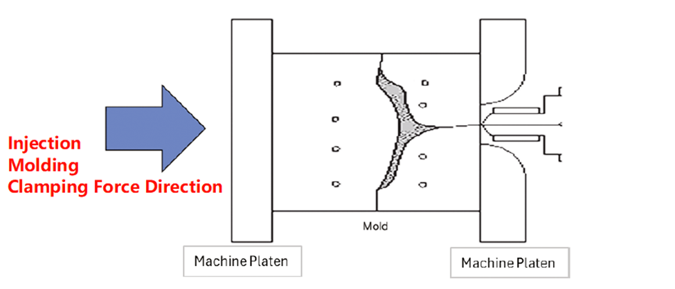
Flash needs similar separation between process and tooling causes. High packing pressure, excessive melt temperature, or insufficient clamp force can force material through an otherwise acceptable shutoff. Worn parting surfaces, damaged inserts, contaminated shutoffs, or loose components can create flash even at validated settings. A supplier compares defect location with mold condition and process history before changing parameters because lowering pressure enough to remove flash can create sink or incomplete packing elsewhere.
Quality control then tests whether the approved process remains stable across production lots. First-article inspection may use calipers, micrometers, optical systems, CMMs, pin gauges, thread gauges, or custom fixtures depending on tolerance and function. A drawing tolerance of ±0.05 mm cannot be managed reliably with a measurement method whose own variation is close to the same range, so gauge resolution and repeatability are part of the inspection plan.
For higher-volume programs, SPC can track critical dimensions or process measurements across samples rather than waiting for a rejected shipment. Cp and Cpk are widely used capability measures, with many customers requesting Cpk targets around 1.33 for established characteristics and higher targets for selected safety or high-risk dimensions. The target depends on customer requirements, measurement quality, sampling method, tolerance design, and whether the process is statistically stable.
Traceability connects inspection results back to manufacturing conditions. A production record may include resin lot, colorant lot, machine number, mold ID, cavity number, operator, date, shift, approved parameter set, maintenance history, and inspection results. If one cavity in a 16-cavity mold starts producing a dimensional change, cavity-level records allow the supplier to separate a local tooling issue from a machine-wide processing issue.
A Reliable injection molding partner should therefore be able to explain how a defect is prevented in measurable terms: acceptable moisture before processing, allowed mold-temperature range, defined transfer position, verified gate-freeze time, cavity-balance results, cooling conditions, sampling frequency, and reaction limits. “Experienced operator adjustment” is not a substitute for recorded process limits.
Maintenance closes the loop between validated tooling and later production. Glass-filled polymers, high-temperature materials, corrosive flame-retardant grades, and high-volume molds can wear gates, vents, slides, shutoffs, ejector bores, and cavity surfaces at different rates. Inspection after 25,000 or 100,000 shots may be appropriate for one mold and unsuitable for another, so intervals are normally based on tool construction, resin, historical wear, and part requirements rather than a fixed universal number.
When a defect still appears, the response should use recorded data from before and after the change. If sink begins after a resin-lot change, compare part weight, viscosity-related fill behavior, cushion, hold response, and moisture history. If burn marks start after 80,000 shots, inspect vents and deposits before rewriting the entire process. If warpage changes after cooling maintenance, compare flow rate and temperature balance across the mold. Repeated parameter adjustment without a documented cause can keep parts running for a shift while making the process harder to reproduce on the next production lot.